How do errors in 3D scanning affect reverse engineering? This analysis examines the causes of scan data inaccuracies, their impact on CAD models, and solutions to control these errors, helping businesses ensure technical accuracy.
In the digital transformation of manufacturing, 3D scanning has become a crucial tool for businesses to collect geometric data from real-world products for reverse engineering, measurement, and technical improvement. However, many reverse engineering projects fail to achieve the desired results, even though the scanned data looks visually appealing.
The core reason often lies in errors in 3D scanning. When the input data is not accurate enough, the entire reverse engineering process is affected. Therefore, understanding how 3D scanning errors affect reverse engineering is a crucial step in helping businesses avoid technical risks and optimize implementation costs.
3D scanning errors are the difference between the actual geometry of an object and the digitized data obtained after the scanning process. Every measurement system has a certain degree of error, even high-precision industrial 3D scanners.
Errors depend not only on the equipment but also on the scanning method, the measurement environment, and the data processing procedures after scanning. When this data is used for reverse engineering, even small discrepancies can have significant consequences in the CAD model.
Reverse engineering is the process of recreating a CAD model from a real product when the original technical drawings are no longer available. This entire process relies on 3D scan data as its foundation.
This means that the quality of the CAD model depends directly on the accuracy of the scan data. If the data is inaccurate, the design engineer will have to manually correct it or even rebuild the model from scratch.
Therefore, how errors in 3D scanning affect reverse engineering is not just a matter of measurement but also determines the effectiveness of the entire engineering project.
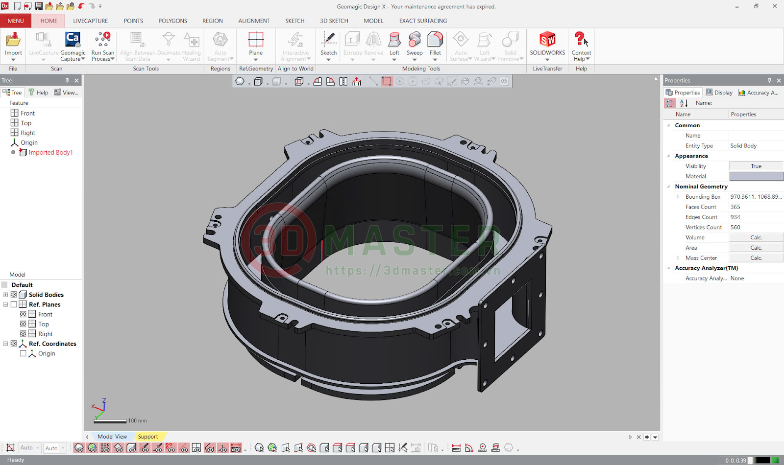
CAD model built from 3D scan data during reverse engineering.
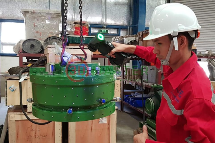
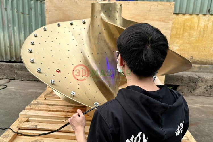
Each 3D scanning system has different accuracy limits. Common equipment often struggles to measure metal details, reflective surfaces, or complex geometries. Meanwhile, industrial scanners are designed to reduce noise and maintain measurement stability.
Choosing the wrong equipment is a common reason why data does not meet reverse engineering requirements.
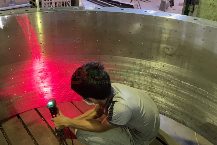
Vibration, strong light, temperature changes, or overly glossy surfaces all affect the scanner's ability to capture data. These factors create noise and reduce geometric accuracy.
A complete scanned model is usually assembled from multiple different scans. If the alignment process is not optimized, errors will accumulate throughout the entire model.
Raw data needs to be filtered for noise, surface reconstruction, and mesh structure optimization. If processed incorrectly, the original geometry may be distorted in ways that are difficult for the user to perceive with the naked eye.
The biggest impact of errors occurs when creating CAD models. The design software will interpolate the geometry based on the mesh data. When data contains discrepancies, common problems include:
Very small errors at the scanning stage can make the part impossible to assemble or machine accurately in production.
3D scan errors don't just exist individually but tend to accumulate throughout the engineering process. Initial discrepancies lead to incorrect CAD models, which in turn affect technical drawings, machining, and product quality control.
This is why many businesses have to redo entire projects even if the error originated from the initial scanning step.
A common misconception is judging scan quality based on the displayed 3D image. A smooth-looking model doesn't necessarily mean accurate data.
Scanned data used for reverse engineering needs to ensure measurement accuracy, stable mesh structure, and efficient CAD surface rendering. If only display optimization is prioritized without error control, the data is virtually unusable for engineering applications.
To effectively control errors, the scanning process needs to be built around the intended use of the data from the outset. Engineers must define tolerance requirements before scanning, rather than processing them after completion.
Using industrial 3D scanning equipment, applying appropriate scanning strategies, and checking for data discrepancies are key factors in ensuring high accuracy of CAD models.
Furthermore, post-processing plays a crucial role in removing noise and normalizing geometry before moving on to reverse engineering.
At 3D Master, 3D scanning is implemented as a comprehensive engineering solution rather than simply providing scan data. Each project begins with an analysis of the data's intended use, such as reverse engineering, measurement, or product improvement.
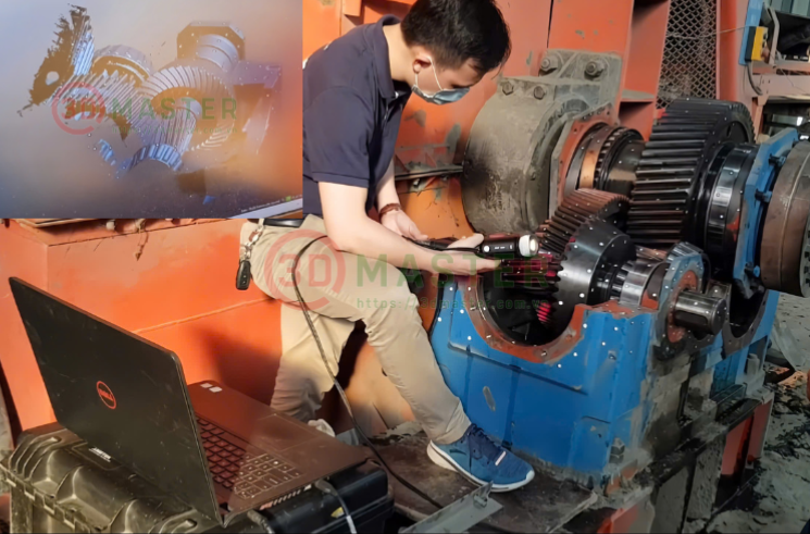
Our engineering team utilizes the high-precision FARO Creaform industrial 3D scanning system to ensure data stability in real-world environments. Error control is implemented throughout the entire process, from data collection to post-processing and accuracy verification before CAD creation.
As a result, the scanned data is not only illustrative but can also be directly applied to design and manufacturing.
Errors become a critical factor when projects involve reverse engineering of mechanical parts, restoring components without existing drawings, checking assembly tolerances, or improving existing products.
In these cases, the scanned data serves as the foundation for the entire subsequent engineering process, so controlling errors from the outset is essential.
The impact of 3D scanning errors on reverse engineering is a core issue determining the success of a reverse engineering project. Accurate scan data shortens CAD rendering time, reduces manufacturing deviations, and enhances engineering reliability.
Businesses need to view 3D scanning as a complete engineering measurement process rather than just a visual 3D modeling step. When errors are properly controlled, reverse engineering becomes a powerful tool for optimizing design and increasing production efficiency.
If your business needs reverse engineering from a physical model or wants to ensure highly accurate scan data for production, contact 3D Master to have our team of engineers advise you on the 3D scanning solution that best suits your technical requirements and practical application goals.
See also: High-quality 3D scanning services at good prices at 3D Master
Hotline - Zalo - LINE - Telegram - WhatsApp - Viber - Kakaotalk: +84 982 089 198 | 0986333960
Email: cuong3dmaster@gmail.com | hung3dmaster@gmail.com | tech3dmaster@gmail.com
Website: https://3dmaster.com.vn